PRS Construction Corner
Building your own Equipment can be SIMPLE and FUN. These pages will detail the Club’s current projects and provide some tips for starting your own. Whatever your level of skill, help and guidance will be freely available to make a success of your work, so don’t be afraid, jump in and get started, build something and we guarantee you’ll not regret it!
Safety Consideration for YOU and Your Project
Building Techniques
- Making your own circuit Boards
- Dead Bug
Projects in the Pipeline
- Arduino Controlled Direct Conversion Receiver.
- Computer to Rig Interface (for PSK31 etc.)
- Morse Code Sounder Version 2
- Frequency Counter – VK3BHR Design
- Iambic Keyer for Morse Paddle – K1EL Design
- Variable Voltage Power Supply
“Where do I start”, I’ve no parts and no equipment, I know nothing…….HELP!
- Sourcing Parts (on the cheap)
A List of Kit Suppliers (not complete!)
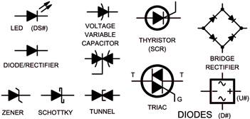
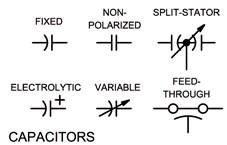
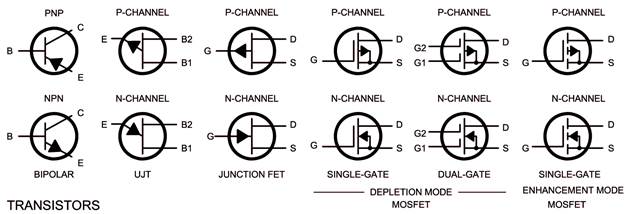
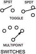
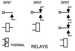
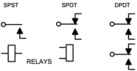
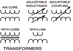
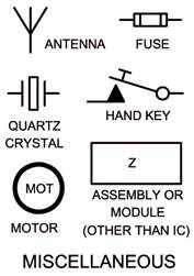
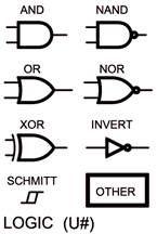
Common Schematic Symbols
Arduino Controlled Direct Conversion Receiver.Project Description – Good introduction to Arduinos, code
easily modified, easily built in stages. An excellent, stable amateur band
vfo will be built as part of the project. Good training in filter
construction and tuning for best bandwidth. An introduction to spectrum analysers
will be given.
|
PSK Mini TransceiverProject Description – A simple, no frills introduction to
digital transmissions, PSK31, RTTY and others. This could be your first
transceiver.
|
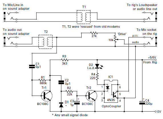
Computer to Rig InterfaceProject Description – A general purpose interface for your
transceiver to PC; enabling the transmission and reception of digital modes,
PSK31, CW etc. Provide electrical
|
Morse Code Sounder – Version 1Project Description
|
Morse Code Sounder – Version 2
|
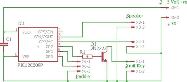
Iambic Keyer for Morse Paddle – K1EL DesignProject Description - Uses a microprocessor PIC chip, this
will be programmed in the Club and guidance will be given on doing this.
Great as an introduction to using PIC chips…. DON’T BE PUT OFF, IT’S EASY!
|
Frequency Counter – VK3BHR Design
|
Crystal CalibratorProject Description - Uses 2-3 integrated circuits, a crystal
and a few other components.
|
|
Audio AmplifierProject Description – A great addition to any experimenters
shack, test out that newly built receiver, add to a simple regenerative
receiver, add your morse audio oscillator…… A full description below.
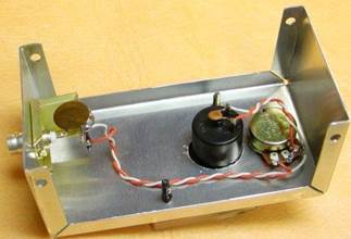
A Handy Audio Amplifier
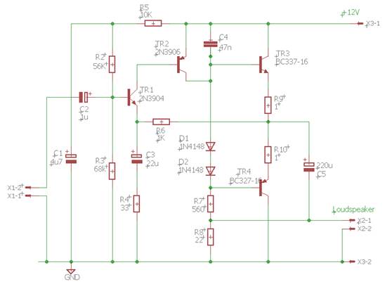
One of the most useful items out of the legion of 'bits' that come in handy for anyone building bits and pieces of their own equipment is a 'universal' audio amplifier. This is one that will perform quite well, but will not break the bank. The circuit is shown in the circuit diagram on these pages. It consists of a complimentary pair (though they don't need to be matched absolutely) of transistors in the output (Tr3 & 4), driven by another complementary pair of transistors Tr1 & 2.
You may find the way that Tr1 & 2 are connected, in a rather strange or unusual way. But in this way, it's possible to minimise the voltage losses, in a comparatively low voltage supply. Although shown as a nominal 12V (13.5V from {PSUs) the circuit will still work down to around 6V with somewhat reduced output volume and quality. The overall voltage gain of the circuit is generally decided by the ratio of two resistors, R4 and R6, in that the voltage gain is around 30:1 as shown (1000/33). If we say that the peak to peak output voltage is around 10V (probably nearer 8-9V) then the input needs to have around one thirty-third of this – or some 300mV or around 100mV RMS. By shorting out resistor R4, with a smaller value resistor the gain will increase, but the audio quality and background noise will also increase. It's difficult to give definitive figures for gain under these circumstances, but with R4, = short, it could be a voltage gain of several hundred, giving a useable output from a simple diode detector circuit.
So, how does the
circuit work theoretically as shown (don't worry it's not going to be too
technical)! The two resistors R1 and R2 work to give a voltage of just half
the level of the power supplies value when taken into account with R5. Let's
assume that the PSU is 13.5V so the voltage at the base of Tr1 is some 6.25V.
The emitter of Tr1 connected directly to R6
The small current passing through Tr1 is also fed directly into the base of Tr2, which amplifies it to flow through R7 and D1 & D2. Resistor R8 is in parallel with the loudspeaker, and takes a proportion of the audio output, but helps to give better quality overall. Capacitor C4 helps to reduce the high frequency hiss that many simpler audio circuits can have. The two diodes D1 & D2 set up a small forward voltage to bias transistors Tr3 and 4 slightly into a more linear mode. If you left these out the amplifier would still work, but would sound very rough and 'gritty' due to a type of distortion called 'Crossover Distortion'. As the sound level gets smaller the proportion of distortion and 'grittyness' gets apparent.
All that the transistors Tr3 and 4 do is act as a double-emitter follower circuit to match the output of Tr2 into the lower impedance of the loudspeaker. The positive voltage feedback though C5 to the resistor R8 and across the loudspeaker, gives a better gain linearity to the circuit. It does this by apparently increasing the gain linearity of Tr1 and Tr2's linear gain.
The circuit can be adapted (built) for differing output conditions. Transistors Tr1 & 2 are simple 'small-signal' devices that that can have maximum currents of only a few milliamps. Though Tr2 must be able to deal with a peak of around 25-30mA, while Tr1 should have good gain at under a milliamp. For use with headphone output only, you really could use the same transistor types for Tr1 and 3 and similarly for Tr2 and 4. Transistors Tr1 & 3 need not have a maximum power capability of greater than around 300-500mW in this case
If however, you're intending driving a loudspeaker to rather more output, then transistors Tr3 and 4 should have good gain at around at least 1A (preferably higher) and with at least a 5W capability and may even need some heatsinking in some cases. I've outlined some possible transistor types in the tables, with some pictures of pin identifications for those types.
Anyone interested in making one can get suitable transistors from me (costing only a small donation to club funds). Tex
Transistors Headphone / Loudspeaker Q1 2N3904, BC108/9, BC182, BC184, BC548 Q2 2N3906, BC212, BC214, BC558 BFY81 Q3 2N2218, BC640 Q4 BC635, BFY81
|
Variable Voltage Power SupplyProject Description – Will use a mains transformer, fuse,
metered voltage and current (these will be ordered from China, lead time up
to 1 month). Separate outputs for 0-15v (-ish), 12v and 5 v.
|
Anything Else YOU Suggest
If you’d like to build something I haven’t shown above and you need some help, let’s chat about it. We can discuss sourcing the parts; possible circuit building techniques; adapting the circuit for your requirements; enclosing it in a presentable case….
|
|
|

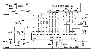 Project
Description - Uses a microprocessor PIC chip and 2 x 16 LCD display to
show Frequency direct from an oscillator and can handle an IF offset either
plus or minus. Will count up to 40Mhz
Project
Description - Uses a microprocessor PIC chip and 2 x 16 LCD display to
show Frequency direct from an oscillator and can handle an IF offset either
plus or minus. Will count up to 40Mhz


Useful Test Equipment
Essential – A Multimeter

$12 from China!

$21 from China
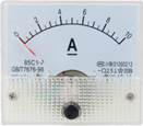
Personally I use an Analogue meter as well which proves useful if there is some fluctuation with voltage/current readings.
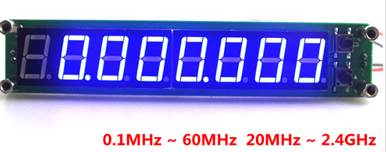
Frequency Counters can be brought from China for around £10, that’s cheap enough to be incorporated in your home built transmitter/receiver and also makes a useful bit of test measuring equipment.
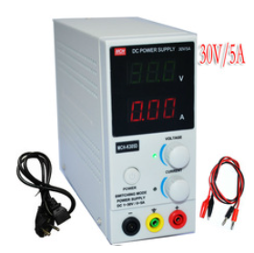
A variable voltage power supply is another useful (essential) addition to your homebrew equipment. They are quite straight-forward to build and can often be found at ‘junk sales’. Ideally it should have a variable voltage output that is current limited AND a 5 and 12 volt output. If voltage and current are shown on internal meters so much the better.

Cheap voltage and current meters can be bought and incorporated into your homebrew power supply.
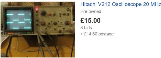
Watch out for second hand Oscilloscopes, they often go ‘begging’ at junk sales and can be had for £10-40 and in my opinion are a most valuable piece of test equipment. They allow you to ‘see’ electricity. You can immediately see if your oscillator is working and can get a rough idea of the frequency. You can also see the quality of the waveform…. A nice pure sine-wave, or full of harmonics and NOT for transmitting. Don’t worry about learning how to use your scope, you’ll quickly grasp the essentials to really improve your diagnostic skills.
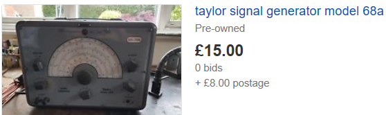
A Signal Generator, either homebrewed or a piece of second (third, fourth etc.) user equipment provides a useful reference signal for testing out your newly constructed receiver. Often an old sig genny can be more useful that a highly accurate digital one as you can quickly spin the dial through a wide span of frequencies while listening on your receiver. Both sig. gennys have their uses.

Essential Tools
So, you are new to building your own circuit boards…. It’s a daunting prospect isn’t it…. why should you bother it’s all too much hassle, sit back and have an easy life!
NO, get up and make a start, it’s fun, exciting and when your project works the sense of accomplishment is amazing. It doesn’t matter whether it’s a simple crystal set, a ‘paint by numbers kit’ or something you’ve designed and built yourself, THEY ARE ALL FUN and something to be proud of.
The following list of ‘tools’ will give you a start; it’s not exclusive and can be varied in terms of quality, cost and where you purchase from. Amateur radio ‘junk sales’ are a good place to start.
For building onto a circuit board
|
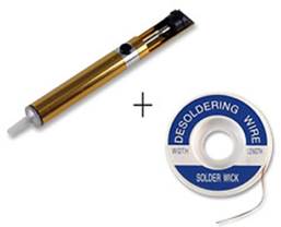
Solder sucker / De-soldering braid |
|
£6 |
|
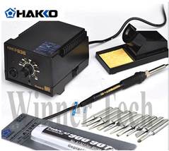
A soldering iron and solder, ideally a temperature controlled iron with several bits. |
|
$40 |
|
Wire cutters, Long nose pliers and similar tools. Small 4-5” tools are great. (Try InExcess shop in Parkstone, Wilkos do a set for £5 or 6) |
|
£8 |
|
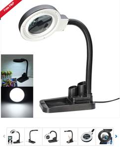
A bench magnifier and source of light (unless your eyes are better than mine…., component marking and colour codes can be VERY small!) |
|
£12 |
|
B&Q etc |
Use fine grade 600 / 1000…..
|
£6 |
|
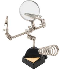
Helping Hands these are terrific for holding small printed circuit boards and/or components while you solder them. |
|
£5 |

For Circuit board making
|
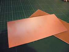
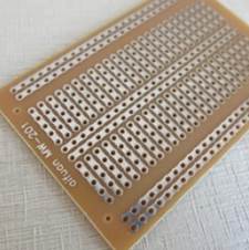
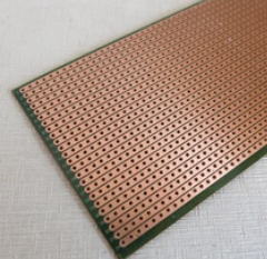
Copper laminate board. Probably get single sided board to start with, either fibre glass (more expensive) or paper resin type (cheaper, just as good) |
|
£Various |
|
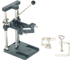
(needn’t be Dremel, there are others that will be just as good and cheaper, watch out for ‘shaft wobble’ you want a drill that will keep a small drill bit straight without shifting from side to side!)
|
|
£25 |
|
Drill stand (Best to try before buying, You want one with no ‘wobble’ as small drills can break easily!) |
|
£25 |
|
A selection of small drills 1.5mm, 1mm, 0.8mm |
|
£Various |
|
Etchant chemical |
Ferric Chloride (or Ammonium Persulphate, Potassium Persulphate). Ferric Chloride stains easily, GREAT CARE needed!!!! Read the MSDS for any chemical chosen. |
£Various |
|
Optional – Brasso, Fine tipped permanent marker, Spray Lacquer |
Brasso gives the board a quality shine, pens for marking component positions on the board and the lacquer ensures it stays there! |
£5 |

Sourcing Parts on the Cheap
1. Scrounge old, broken radios, tvs and other electronic equipment and de-solder the parts.
2. Go to Amateur Radio junk sales and haggle!
3. Team up with a mate and buy in bulk from China through Ebay or AliExpress. Also consider UK suppliers.
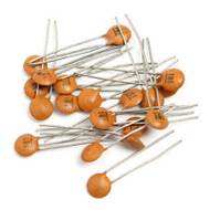
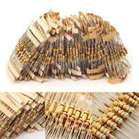
10 of each of 100 values (ie. 1000 components in total), either resistors or capacitors for about £6
Keeping Parts Organised
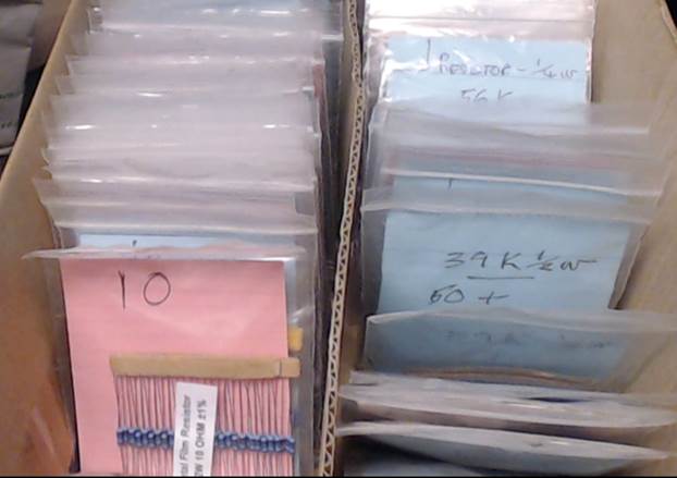
There’s no ‘one-answer’ to this problem, a keen constructor will acquire many thousands of parts over the years and if you don’t keep them in some sort of order it will take ages to find the part you need.
I use a combination of cheap solutions. 1. Keep old butter plastic containers for larger parts. Ice-cream tubs and the like are equally useful. 2. Buy a pack of 3” x 5” sealable plastic wallets (shown above), they are cheap and with a small cardboard insert cut from a cerial box can be used to hold resistors, transistors and the like.
Teach the wife colour codes and enlist her help in sorting parts into the correct bags, the strong possibility is that she will be better at it than you!
Circuit Building Techniques
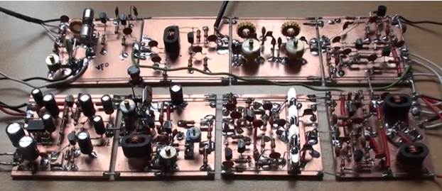 2.
2. 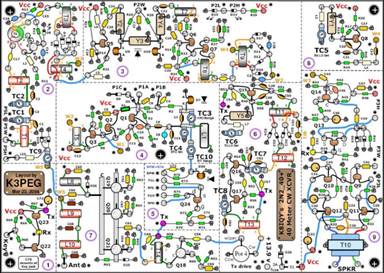 The
circuit above was built by PA1ED using Manhattan Island techniques; note also
the wise use of separate modules for the different stages of the BITX20
transceiver design. No chemical etching, components either soldered to pcb
ground plain or soldered to small pcb islands….look carefully at the .2” by
.2” pieces of pcb superglued to the main pcb to provide isolated soldering
points. Needs careful layout, can be very quick to construct.
The
circuit above was built by PA1ED using Manhattan Island techniques; note also
the wise use of separate modules for the different stages of the BITX20
transceiver design. No chemical etching, components either soldered to pcb
ground plain or soldered to small pcb islands….look carefully at the .2” by
.2” pieces of pcb superglued to the main pcb to provide isolated soldering
points. Needs careful layout, can be very quick to construct. 


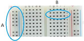 The
vertical tracks (A) with the red and blue lines at the side of each are all
connected and meant for a +ve or -ve connection to the power supply.
The
vertical tracks (A) with the red and blue lines at the side of each are all
connected and meant for a +ve or -ve connection to the power supply.

Safety Considerations for YOU and Your Project
Protecting You
The least ‘obvious‘ of accidents can happen, believe me, I’m old enough to have seen some unbelievably daft/impossible accidents. Here are a few pointers for you:
1. Keep your work-area uncluttered.
2. Keep drinks safely to the side of your word, away from cables or anything that might cause them to spill.
3. Keep mains electric wires away from causing trip hazards.
4. Don’t stretch mains wiring.
5. Use appropriate fuses ….not a 13amp fuse in place of a 3amp etc.
6. Soldering irons can cause nasty burns, use common sense.
7. Some soldering iron stands are flimsy and dangerous, ensure the stand is either heavy (not likely to tipple over), or secured to your workbench.
8. Check your work for short circuits before connecting a battery and always have a multi-meter in circuit measuring current for first switch-on.
9. The voltages we will be using for small transistor projects are likely to be low but a short on a high capacity battery can still be dangerous, TAKE CARE.
10. Children are fantastic, especially when kept at a distance!
This list isn’t exclusive, but the Club values your membership, look after yourself.
Protecting Your Project
1. Some devices are static sensitive, ensure you use an earth strap when dealing with these devices.
2. Practice your soldering techniques, follow advice given at the Club and don’t ‘cook’ your circuit board or components.
3. Never be afraid to ask for advice and guidance from Club members, it will always be freely given.
Kit Suppliers
(not complete, send additions to Paul)
|
Poole Radio Society has no control over the content of these external web sites many of which will store cookies on your computer.
Walford Electronics Web Site - http://www.walfords.net/
Notes – Tim provides a range of kits to suit all skill levels, typically provision of a suitable case is left to the builder. Tim attends several radio rallies and can be found year on year at the Yeovil Radio Rally.
|
|
QRP-Labs Web Site - http://qrp-labs.com/
Notes – A range of excellent value kits using ‘state of the art’ technology, possibly not for the first time builder.
|
|
HF Signals Web Site - http://www.hfsigs.com/
Notes – Produces an excellent SSB Transceiver kit at a terrifically low price, ready built and aligned and just needing a suitable case to your design. Many modifications available.
|
|
Elecraft Web Site - http://www.elecraft.com/
Notes – World class transceiver kits, expensive, but if your pockets are deep take a look!
|
|
JUMA Amateur Radio Kits Web Site - http://www.jumaradio.com
Notes – An excellent range of receiver/transceiver kits, not for the first time builder.
|
|
Kit Radio Company Web Site - http://www.kitradio.co.uk
Notes – A range of simple, suitable-for-beginners, receiver kits.
|
|
Radio Kits Web Site - http://www.radio-kits.co.uk/
Notes – A range of amateur radio kits.
|
|
Kits and Parts dot Com Web Site - http://kitsandparts.com/
Notes – A US supplier of a range of useful amateur radio parts (notably toroid’s) and a few transceiver kits.
|
|
Oak Hills Research Web Site - http://www.ohr.com
Notes – A range of superb, albeit expensive amateur radio transceiver kits.
|
|
Vectronics Web Site - http://www.ohr.com
Notes – A range of basic (beginner) receives and transceivers.
|
|
Spectrum Communications Web Site - http://www.spectrumcomms.co.uk
Notes – A local (Dorchester) supplier of useful amateur radio kits and parts.
|
|
Ebay, AliExpress Web sites - http://www.ebay.co.uk/ and https://www.aliexpress.com
Notes – There are a good many very cheap Chinese copies of well known simple transceivers…..they are very cheap indeed but the documentation is in ‘Chin-glish’ so be prepared. Nevertheless they are great for starters and Club help is always available. Use ‘Ham Transceiver kit’ as a possible search criteria. |
Common Schematic Symbols
|
|
|
|
|
|
|
|
|
|
|
|
|